SAFETY IS NOT AN ACCESSORY. IT IS THE SYSTEM.
Hydrogen service safety depends on coordinated engineering. Marathon designs the bay architecture, detection, airflow, exhaust, alarms, interlocks and controls to work together as a layered response to a potential hydrogen release.
The Nature of the Challenge
Hydrogen is much lighter than air and can disperse rapidly when released. In an enclosed maintenance area, ceiling geometry, obstructions and airflow can still allow hydrogen to collect near high points. The bay architecture, detection system and ventilation strategy must be engineered together to manage that risk.
This is why third-party peer reviewed, coordinated engineering is critical to providing a safer service environment for your team.
THE LAYERED SAFETY APPROACH
Seven coordinated steps engineered to manage potential hydrogen releases.
DIRECT
A purpose-built hood and containment strategy direct rising hydrogen toward the engineered exhaust path.
DETECT
Hydrogen sensors continuously monitor the service environment at engineered locations.
RESPOND
The Smart control panel initiates the approved alarm and ventilation sequence when setpoints are reached.
ISOLATE
Applicable interlocks isolate designated ignition sources or equipment according to the engineered control sequence.
EXHAUST
The ventilation system moves the released gas toward an approved outdoor discharge location.
ALERT
Visual and audible alarms notify personnel of the detected condition and system response.
VERIFY
Commissioning confirms the installed safety functions included in the approved project scope.
Hydrogen Service Bay Air Flow
Air is drawn upward inside the enclosure, moving toward the engineered exhaust hood. This controlled updraft captures any released hydrogen gas, safely channeling it away from the vehicle and personnel.
The gas then travels up through the ducting and is discharged outdoors above the roof line in accordance with the engineered project design. This consistent, engineered airflow supports a safer working environment.
Every application is different. Airflow, exhaust routing and discharge location are engineered around your vehicles, your bay and your building.
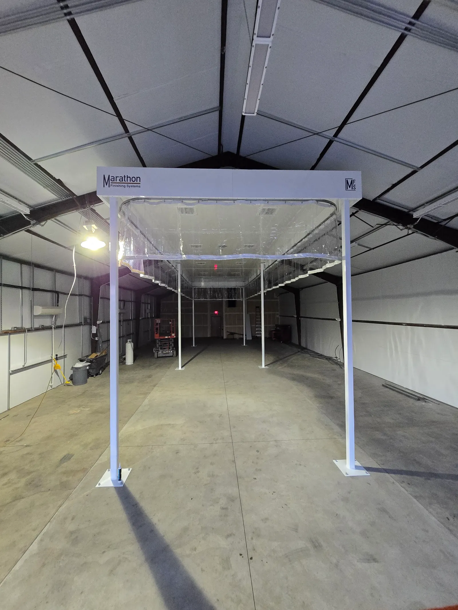
Standard Components
Industrial components selected around the application, engineered design, and local requirements.
Fans & Motors
Spark-resistant exhaust fans run continuously and ramp up to purge the moment hydrogen is detected.
Rugged Exhaust Hood
Steel capture hood with bolted construction built to withstand industrial use and guide airflow effectively.
Curtains or Enclosure Walls
Depending on the application, the bay is enclosed by Goff's fire-retardant industrial curtains or solid enclosure walls. Either way, released hydrogen is directed up into the capture hood.
Hydrogen Sensor
Industrial hydrogen detection from RKI Instruments, positioned where rising hydrogen collects. The bay is monitored continuously, and detection triggers the purge, alarms and interlocks automatically.
Classified LED Lighting
UL Certified Class I, Division 2 (C1D2) fixtures provide brilliant illumination with minimal shadowing.
Smart Control Panel
Marathon's exclusive automated control coordinates ventilation, alarms, and interlocks.
From Design to Verification
Safety has to work in your building.
The hood, sensors, fans, alarms, and controls are parts of one response. Their locations and interfaces depend on the vehicles being serviced, the work being performed, and the facility around them.
Third-party peer review is part of the design story. Local approval and verification of the installed system are separate project steps. Marathon works with your team and licensed engineering partners to define the required documentation and commissioning scope.
Explore the standards we engineer toWhat a design review covers
- Vehicle dimensions, hydrogen storage locations, and approved service procedures.
- Capture hood and enclosure geometry, ceiling obstructions, and the exhaust path.
- Detection locations, control sequence, alarms, and equipment interlocks.
- Exhaust discharge, replacement air, utilities, and building system interfaces.
- Applicable code editions, local fire and building official requirements, and the permit scope.
- Commissioning records, training, maintenance instructions, and responsibility at handover.
Commissioning & Operations
The handover is part of the system.
Qualified personnel verify the agreed detection, ventilation, alarm, and interlock responses using the approved commissioning procedure. Keep the acceptance record, operating instructions, and maintenance requirements available to the team responsible for the bay.
Operating and emergency procedures must come from the approved project documentation and vehicle manufacturer. Website information is an introduction to the system.
Ready to evaluate your facility?
Schedule a consultation to discuss your specific infrastructure needs.